PML Series High impedance & 50Ω passive probe
|
|
|
|
|
|
|
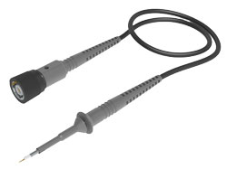
PML 711/721 high
impedance probe |
|
|
|
|
|
|
|
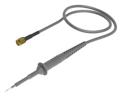
PML 50 Ω probe |
|
■ 2.5mm probe
tip |
||
|
|
|
|
|
Example |
|
|
■ Probe |
■Insulating
Cap 2.5 |
![]()
|
There are two
types of PML series passive probes, high impedance
(10 MΩ) specifications and low impedance
specifications (500 Ω/5 kΩ). We also have many
tools to avoid probing troubles due to high integration of LSI. .. For example,
do you suffer from shorting with the next IC pin during probing? Also, is the
signal to be measured output from the IC far from the ground? Do you want
to measure two or more signals at the same time? |
![]()
|
|
|
|
|
2 foot positioner (893-250-001) |


![]()
![]()
|
■ |
accessories |
|
|
|
|
![]()
|
■ |
About probe
calibration |
|
We recommend
that you calibrate the probe before using it. |
|
|
|
![]()
|
||||||||||||||||||||||||||||||||||||||||||||||||||||||||||||||||||
*Please
contact us for orders other than RO (with lead-out pin).
PML Series High impedance & 50Ω passive probe
|
|
|
|
|
|
|
PML 711/721 high
impedance probe |
|
|
|
|
|
|
|
PML 50 Ω probe |
|
■ 2.5mm probe
tip |
||
|
|
|
|
|
Example |
|||
|
|
||
![]()
|
There are two
types of PML series passive probes, high impedance
(10 MΩ) specifications and low impedance
specifications (500 Ω/5 kΩ). We also have many
tools to avoid probing troubles due to high integration of LSI. .. For example,
do you suffer from shorting with the next IC pin during probing? Also, is the
signal to be measured output from the IC far from the ground? Do you want
to measure two or more signals at the same time? |
![]()
|
|
|
|
|
2 foot positioner (893-250-001) |
![]()
![]()
|
■ |
accessories |
|
|
|
|
![]()
|
■ |
About probe
calibration |
|
We recommend
that you calibrate the probe before using it. |
|
|
|
![]()
|
||||||||||||||||||||||||||||||||||||||||||||||||||||||||||||||||||
*Please contact us for orders other than RO (with
lead-out pin).